
1. Introduction to stress corrosion cracking
Stress-corrosion cracking (SCC) of material refers to cracking caused by the simultaneous presence of tensile stress and a specific corrosive environment. stress corrosion cracking happens due to localized corrosion, there is no any uniform corrosion in case of stress corrosion cracking.
1.1 Stress:
Generally cracking in material takes place at the stress level equal to the fracture stress or UTS of that material but when material is exposed to some specific corrosive environment which increases the susceptibility of that material to stress corrosion cracking, then required stress level for cracking could be below the yield stress value of that material.
1.2 History:
Many explosions of riveted steel boilers occurred in early steam-driven locomotives. During 1865 to 1870, 288 boilers exploded in UK and during 1867 to 1868, 441 boilers exploded in USA. In riveted joint cold work produces stresses at joint. Boilers are made up of steel so water used should be of high PH level to eliminate the corrosion of steels. They used water of around 10 PH level by adding sodium hydroxide to water. When evaporation of water occurs, it becomes steam and sodium hydroxide concentration of remaining water in boiler increases with time. So, combination of high stresses at rivet joints and high concentration of sodium hydroxide leads to cracking, that named as caustic embrittlement.
One such failure of steel boiler shown in figure 2 below, in which crack can be seen through the rivet holes. Crack indicated by black arrows.

2. Crack morphology:
Stress corrosion cracking is brittle in nature. It is brittle because in stress corrosion cracking, the stress levels are generally below the yield strength in corrosive environment, so no any plastic deformation occurs.
On a microscopic scale, stress corrosion cracking in normally ductile materials produces brittle-intergranular or cleavage-like (trans granular) fracture surfaces, in contrast to dimpled fractures produced by fast fracture in inert environments. Intergranular cracks propagate at grain boundary, while trans-granular crack cuts across the grain as shown in figure 3 below.
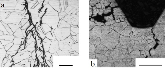
Crack branching is a feature of stress corrosion cracking which can be seen in figure 3 above.
3. Factors affecting stress corrosion cracking:
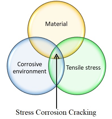
As explained in the Venn diagram, stress corrosion cracking depends upon material, corrosive environment and tensile stresses. So, to understand the factors affecting stress corrosion cracking, we need to understand metallurgy of material that used for a given application, the environment in which material is exposed and the nature of tensile stress. All these are going to govern the susceptibility of a material towards stress corrosion cracking.
3.1 Tensile stress:
It can be applied tensile stress or residual tensile stress. Residual stress can be produced in material if it is welded, if material goes under cold working (say wire drawing), if material gone through thermal stresses. Also, residual stress can also come from corrosion product accumulation in system.
Let us know how corrosion product accumulation leads to residual tensile stress by an example of heat exchanger. In heat exchanger you would have tube and tube sheet. Tubes are joined with tube sheet by welding on one face, generally outside face welded and the inside face not welded, so, there is annular space inside. So in annular space liquid say environment penetrates and comes in contact with material, say steel. Which leads to steel corrosion product formation, iron hydroxide. Volume of iron hydroxide is more than iron, so annular space gets expanded and tube will dent inward. This denting will produce high residual tensile stresses at tube which add to the applied stresses. These high stresses can lead to cracking.
Now let us consider the effect of stress level on stress corrosion cracking. Increasing the stress, decreases the time before cracking, means it increases the susceptibility towards stress corrosion cracking. There is some minimum stress level below which stress corrosion cracking not occur for long period, which is called Threshold stress. Threshold stress depends upon combination of material and corrosive environment. It is used as engineering parameter to design component against stress corrosion cracking.

Threshold stress can be found for material-environment combination by a tensile test of required material which is enclosed in a cell and the cell has required corrosive environment. So, by applying tensile load, we can find threshold stress value as well as other stress level which can lead to stress corrosion cracking at different time. This data of test is shown in figure 4 above.
Threshold stress is used as engineering parameter to design that consider crack initiation.
Crack initiation and propagation:
Crack initiation generally occur by localized corrosion like, pitting corrosion, crevice corrosion, inter granular corrosion, de-alloying, etc. Since these localized corrosions are slow process which makes crack initiation also slow. If there is loading in this regions and stress levels are beyond threshold stress then stress corrosion cracking initiates. Some crack initiation sites are shown in figure 5.
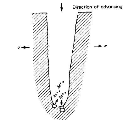
Generally, crack propagates in the perpendicular direction to applied stress as shown in figure 6. As crack propagates the cross section reduces and applied stress is same, so at remained c/s area stress increases and at after sometime this stress level equals or exceeds the UTS value of that material. So just before complete cracking, it fails in ductile manner due to overload. Along with brittle failure we also see some part of sample having ductile failure in most of cases.

(b) Optical micrograph showing crack-initiation from a de-alloyed Mn-rich phase in a Mn-Cu alloy used for submarine propellers
For design that takes care of crack propagation use fracture mechanics as criteria and of course in the corrosive environment for stress corrosion cracking. For crack propagation there is a term called stress intensity factor ( ) at crack tip, which is dependent upon applied stress and crack length value. If value of is equal to which is called fracture toughness then and then crack propagates in normal conditions. But when it is in a corrosive environment then stress corrosion cracking can propagate at (threshold stress intensity factor for stress corrosion cracking) at crack tip which is well below value.

In figure 6, we can see different crack growth with stress intensity factor value. There are 3 regions, region 1 where crack growth starts just above value and crack grow as K value increases. So crack growth depends upon environment and K value. Region 2 where crack growth rate is very slow and it does not depend on K value, in this region crack growth rate depends upon environment. Region 2 is used for design of component to calculate life of it under environment. Region 3 where c/s area is very low due to crack propagation and load on this area become very high that it reaches at crack tip and material fails catastrophically.
If corrosive environment was not present then crack propagates at . but due to this environment crack propagated below so region 1 and 2 are called subcritical crack growth.
Now, back to the factors affecting stress corrosion cracking
3.2 Corrosive environment:
| Material | Environment |
| Austenitic Stainless steel | Chlorine |
| Carbon steels | Nitrates, carbonates, phosphate |
| Copper based alloys | Ammonia |
| Al and Mg based alloys | Chlorine |
Table 1 shows some material that has high susceptibility to stress corrosion cracking in specific environment but these materials are not confined to these environments only. In nuclear industry stress corrosion cracking is observed in stainless steel in pure water also, but time taken to stress corrosion cracking is very high. So, pure water can also induce stress corrosion cracking in stainless steel at temperature and pressure of reactor but over a long period of course.
When we talk about environment this means, the chemical composition, PH value and temperature of it.
Let us understand the effect of chemical composition or concentration of ionic species of environment on the susceptibility to stress corrosion cracking by an example.

Figure 7 shows combined effect of chlorides and dissolved oxygen on the stress corrosion cracking of SS304. In figure we can see failures occurred in the region of high dissolved oxygen content (area above curve) so it is very critical to stress corrosion cracking of austenitic stainless steel. By reducing oxygen stress corrosion cracking can be prevented.
If we talk about temperature of environment then, as seen with the most of chemical reaction, stress corrosion cracking susceptibility increases with temperature. Let us consider a case of caustic embrittlement susceptibility of welded steels at different temperature.
As shown in figure 8, in area A, as-welded carbon steel (CS) doesn’t fail, so no stress relives required here. In area B, at relatively high temperature welded CS can fail, so stress relive action required or SS material can be used to prevent cracking. In area C temperatures are very high so welded CS fail by caustic embrittlement and the only solution in this area is use of Nickle based alloys to prevent cracking.
Figure 8: Effect of temperature on susceptibility of caustic embrittlement of welded steel
3.3 Metallurgy of materials:
It involves alloy composition, microstructure, microchemistry at grain boundary, type of dislocation, etc. Alloy composition and microstructure also control strength, and there is a general trend of increasing stress corrosion cracking susceptibility with increasing strength for many materials, especially steels.
For intergranular stress corrosion cracking of 7xxx Al-Zn-Mg-Cu alloys in aqueous environments, overaging heat treatments decrease strength by only a small extent compared with the peak-aged condition, but can decrease stress corrosion cracking plateau velocities significantly due to changes in grain-boundary microstructure and microchemistry. Shown in figure 9.
In particular, an increase in the Cu content of grain-boundary precipitates is probably responsible for the beneficial effects of overaging.

4. Mechanism of stress corrosion cracking:
Although stress corrosion cracking represents one of the most important corrosion problems, the mechanism involved is not well understood. This is one of the big unsolved questions in corrosion research.
The main reason for this situation is the complex interplay of metal, interface and environment properties. Further, it is unlikely that a specific mechanism will be found that applies to all metal-environment systems. Many mechanisms for stress corrosion cracking of specific metal-environment combinations have been founded, but here one general mechanism is discussed as follows:
4.1 Slip-Dissolution mechanism:
As we know in case of plastic deformation due to dislocation motion, there are slip steps formed on the surface of material which is also called slip lines.
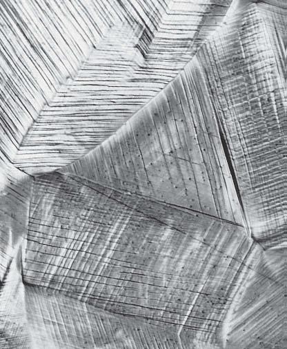
Region immediate to crack tip can go under plastic deformation because there is high stress or stress concentration present at crack tip. As explained slip steps will be formed at the surface of crack tip due to plastic deformation which leads to rupture of passive film present on this surface. So, this passive film rupture at crack tip forms a chemically active path which promotes metal dissolution. So by this metal dissolution crack propagates as shown in figure 11, below.
5. Preventive methods for stress corrosion cracking:
Lowering the stress below threshold value. This may be done by annealing in the case of residual stresses, thickening the section, or reducing the load. Plain carbon steels may be stress-relief annealed at 600 to 650°C, and the ASS are frequently stress relieved at temperature range of 800 to 950°C.
Eliminating the critical environmental species by, for example, degasification, demineralization, or distillation.
Changing the alloy is one practical way, if neither the stress nor the environment can be changed. For example, when 304 SS is not satisfactory then duplex SS or FSS can be used which has more resistance to stress corrosion cracking. For corrosive environment at higher temperature level Nickle based alloys are excellent against stress corrosion cracking, as explained in factors affecting stress corrosion cracking.
Applying cathodic protection to structure with an external power supply or consumable anodes. Care should be taken while applying cathodic protection that it should be assured that the fracture of structure is caused by stress corrosion cracking only. If cause of failure is not well known and if hydrogen embrittlement is present then it gets accelerated by cathodic currents.
Shot pinning of entire exposed surface is also one solution that produces residual compressive stress in the surface of metal. The surface layer under compression is quite thin-usually a few thousandths of an inch. For example, type 316 SS centrifuge which was used to handle organic chlorides at 60°C temperature that failed by stress corrosion cracking after 1 year of service. A replacement of shot pinned 316 SS centrifuge showed no any cracking after 42 months of service. Shot peening of cracked surface is not recommended.
For Readymade Word file report with all images in case study (visual examination, fractography, SEM EDS analysis) + PPT for INR 100 or 1.5 USD, contact us.
Want to learn case study on heat exchanger tube failure due to erosion corrosion? click here
References:
- “Corrosion Engineering” by Mars Fontana, 3rd edition, Mcgraw-Hill
- “Stress Corrosion Cracking Theory and Practice” by V.S. Raja, Tetsuo Shoji, Woodhead Publishing Limited
- NPTEL course-“Aqueous Corrosion and Its Control”-Lecture on “Forms of Corrosion: Stress Corrosion Cracking”, Lecture no. 29, 30 & 31 by Prof. V. S. Raja, IIT Bombay
- Samuel W. Parr and Erederick G. Straub, “The cause and prevention of Embrittlement of Boiler plate”, University of Illinois, Urbana