
1. Introduction to erosion corrosion
The term “erosion” applies to deterioration due to mechanical force. When the factors contributing to erosion accelerate the rate of corrosion of a metal, the attack is called “erosion corrosion”. Erosion corrosion is usually caused by an aqueous or gaseous corrodent flowing over the metal surface or impinging on it.
Erosion corrosion normally occurs under turbulent-flow conditions. The flowing fluid may be single phase as in the erosion–corrosion of copper tubing by potable water. Multiphase flows with various combinations of gas, water, oil, and sand can cause severe erosion–corrosion of oil/gas production systems.
It is characterized by grooves, gullies, waves, rounded holes and valleys and usually exhibits a directional pattern which is sometimes also called ‘fingerprints’.
There is also difference between erosion and erosion corrosion. i.e. there is a pipeline with nitrogen gas in a pipeline and certain solid particles and the tube gets damaged. So, it is a purely erosion damage. But with moisture in a system, and that gas is no more dry, the solid particles are no more dry because thay have some water, now it becomes erosion corrosion. Because there is a corrosion environment component coming over here.
1.1 How it is different from flow assisted and cavitation corrosion
Although some literatures mention them that they are same because their prevention and control measures are similar and overlaping. but fundamentally there is difference in mechanism under which they occur.
Flow induced corrosion is related to mass transfer of corrosion product. How easily it can get removed from surface. It happens mostly in pipelines in thermal power plants. Flow assist the solubility of corrosion products which reduces film formation. i.e. Fe3O4 oxide forms when solubility of Fe3+ and Fe2+ is less than ions. They are dissolving and enrich the film. But when fluid is moving and velocity increases, the dissolution process by sweeping away the corrosion products becomes dominant than film formation.
Cavitation corrosion essentially happens because of implosion of bubbles on the surface of structure and this transfers huge amount of pressure energy on to the structures. pressure exerted can lead to plastic deformation. For cavitation to occur it must have a region of low pressure where the liquid will evaporate and then the evaporated vapor will be subjected to a higher pressure. The pressure is sufficient enough to condense and lead to implosion and that leads to the plastic deformation of the material. This happens in pumps, turbines impellers.
1.2 Examples of erosion corrosion
The erosion corrosion mechanical damage is predominant. Many metals & alloys susceptible to erosion corrosion e.g. aluminum, lead, stainless steels, carbon steels. All types of equipment exposed to fluid are susceptible to this type of corrosion such e.g. piping systems, bends, elbows, tees, valves, pumps, blowers, in the heat exchangers and reaction vessels, especially the inlets.
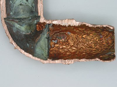
Appearance wise, It appears in the form of grooves, gullies, waves, rounded holes & valleys. They typically show a directional pattern. This is figure showing erosion corrosion of condenser tube wall by water flow. Ultimate perforation due to thinning or progression of pits, and rupture due to failure of the thinned wall to resist the internal fluid pressure are common. All equipment exposed to flowing fluid is subject to erosion corrosion, but piping systems and heat exchangers are the most commonly affected.
2. Mechanism of erosion corrosion
The way in which this corrosion mechanism manifests itself can vary but typically it has two basic features [4]
- The liquid flow removes diffusion limitations and increases the supply of corrosive reagents
- The metal is exposed through mechanical removal of the passivated protective film
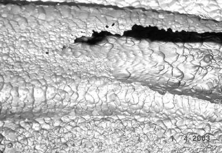
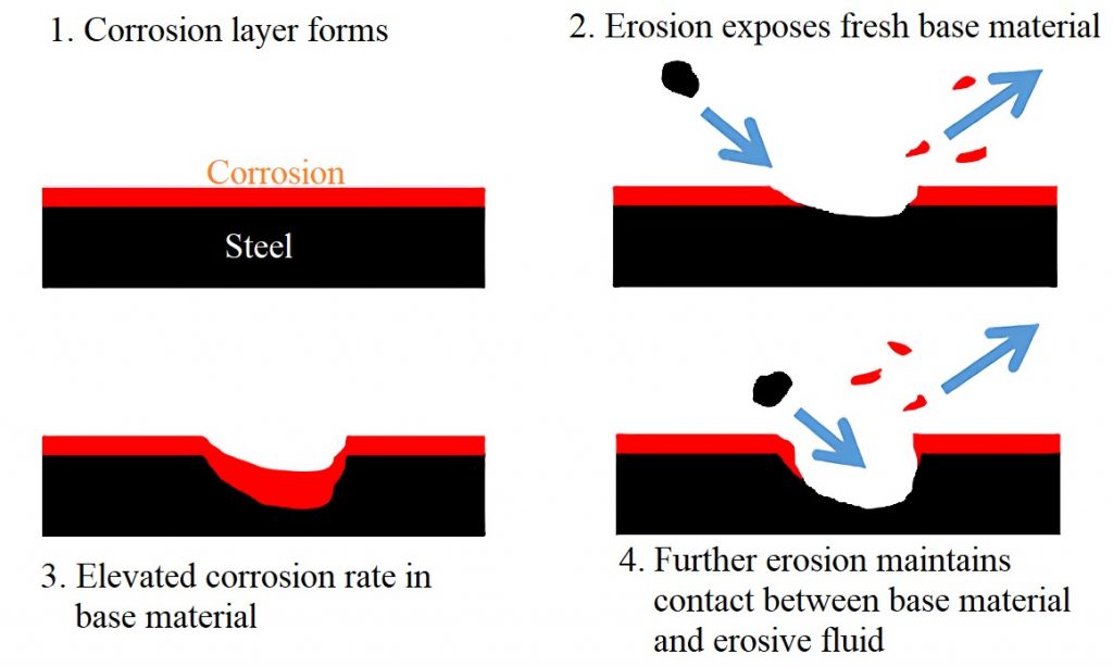
A passive film on a metal is a non-active chemically protective barrier layer between the corrosive substance and the metal substrate, the protective layer typically has low mechanical strength. When this layer is broken off by high velocity fluid flow, or some other impinging material, the metal beneath begins to form another passive layer. When pits are formed (see figure 4 above) this can accelerate the degradation even further by the disruption of the flow, this can cause eddy currents which then speed up the removal of the protective layer.
Furthermore, The sources of the various mechanical forces involved in the erosion of protective films and/or the underlying metal at flow system walls are [3] …
- Turbulent flow, fluctuating shear stresses, and pressure impacts
- Impact of suspended solid particles
- Impact of suspended liquid droplets in high-speed gas flow
3. Factors affecting erosion corrosion
Erosion corrosion is affected by velocity, turbulence, impingement, presence of suspended solids, temperature, and prevailing cavitation conditions. The acceleration of attack is due to the distribution or removal of the protective surface film by mechanical forces exposing fresh metal surfaces that are anodic to the uneroded neighboring film. A hard, dense adherent and continuous film, such as on stainless steel, is more resistant than a soft brittle film, as that on lead. The nature of the protective film depends largely on the corrosive itself. [2]
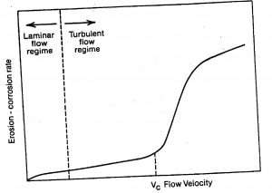
3.1 Turbulence
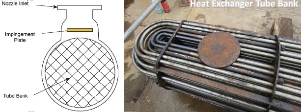
Turbulence is caused when the liquid flows from a larger area to a small diameter pipe, as in the inlet ends of tubing in heat exchangers. Internal deposits in the pipes, or any obstruction to the flow inside a pipe by a foreign body, such as a carried-in pebble, can also cause turbulence.
In turbulent flow there are fluctuating shear stresses and pressures at the wall. The largest values are obtained during quasi-cyclic bursting events close to the wall which are said to be responsible for most of the turbulent energy production in the entire wall-bounded shear flow. film removal in single-phase aqueous flow is invariably associated with the vortices created under disturbed flow conditions produced by sudden macro- or microscale changes in the flow geometry.
3.2 Velocity
In most metals and alloys, corrosion rates increase with increased velocity, but a marked increase is experienced only when a critical velocity is reached. It is material and environment dependent.
| Alloy | Critical shear stress (N/m²) | Critical velocity 25-mm tube (m/s) | “design” velocity based on 50% (m/s) | Accepted maximum design velocity(m/s) |
| Cupro Nickel with Cr | 297 | 12.6 | 8.6 | 9 |
| 70-30 Cupro Nickel | 48 | 4.6 | 3.1 | 4.5-4.6 |
| 90-10 Cupro Nickel | 43 | 4.3 | 2.9 | 3-3.6 |
| Aluminum Bronzes | – | – | – | 2.7 |
| Arsenical Al Brass | 19 | 2.7 | 1.9 | 2.4 |
| Inhib. Admiralty | – | – | – | 1.2-1.8 |
| Low Si Bronze | – | – | – | 0.9 |
| P Deoxidized Copper | 9.6 | 1.9 | 1.3 | 0.6-0.9 |
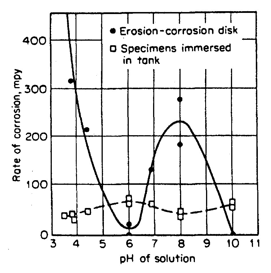
3.3 pH of environment
pH affects films in erosion-corrosion of low-alloy steel. Scale generally granular Fe304 (non-protective). But at pH 6 & pH 10, scale Fe(OH)2/Fe(OH)3. that hinders mass transport of oxygen and ionic species. So maintaining pH of environment for particular metal affects dissolution hence erosion corrosion indirectly.
3.4 Surface film
surface film offers a barrier for corrosion, it also takes the impact of the environment. If film is hard, chance of erosion is less, if film is adherent it won’t easily get ripped off by particles. And if it is Resilient within the elastic limit, this will improve its resistance. Thickness is also critical in this case too thin is not enough and too thick is also becomes brittle in most oxides, so this thickness with optimum density and less porosity ensure that the alloy has a better resistance against erosion corrosion problems.[1]
3.5 Impingement
Impingement, direct contact of the corrodent on the metal surface, occurs at bends, elbows and tees in a piping system and causes intense attack. Impingement is also encountered on the surface of impellers and turbines in areas in front of inlet pipes in tanks and in many other situations. The attack appears as horseshoe-shaped pits with a deep undercut and the end pointing in the direction of flow.[2]
Solid-particle impacts can damage both types of protective films (thick diffusion barriers and thin passive films) leading to erosion–corrosion. The particles may also erode the underlying metal, adding to the overall metal loss. the erosion rate ER is a function of the kinetic energy of the particles and the frequency of impacts. The kinetic energy of the particle normal to the wall will be determined by the impact velocity and impact angle along with the particle density and size. The shape of the particle and the microroughness of the particle surface influence the effective forces generated at the wall by the impact. The damage done will be strongly related to the relative hardness of the impinging particles and the flow system walls.
Erosion by impinging liquid droplets carried in high-speed vapor or gas flows is usually called liquid impingement attack. The attack involves the exposure of the solid to repeated discrete impacts by liquid droplets which generate impulsive and destructive contact pressures far higher than those produced by steady flows. Impingement erosion has been a problem with low-pressure steam turbine blades operating with wet steam and rain erosion of aircraft and helicopter rotors.
Cavitation attack subset of erosion is the result of the violent collapse of vapor cavities, or bubbles, <1mm diameter that are formed in a flowing liquid when the hydrostatic pressure drops below the vapor pressure of the fluid. The cavities are carried downstream to higher pressure regions where collapse occurs. The dynamic forces associated with the collapse of the cavities at the walls of the system lead to high-frequency fatigue-stress damage. The shock waves from spherical collapse and microjets from asymmetrical collapse have both been suggested as the cause of the damage.[3]
4. Prevention of erosion corrosion
- Implementing proper design
- Avoid turbulence wherever possible, if unavoidable try to minimize by design
- Keep radius of bends higher and smooth
- Use linings of smooth material wherever process permits
- Use baffles to reduce impingement impact forces
- Use filters to remove undesired particles
- The tubing should be reamed where it is pushed into fittings such as elbows prior to soldering to mitigate the erosion-corrosion
- Changing the local geometry: for example, installing a larger control valve to reduce downstream turbulence
- Reduce the process velocity to optimum and less than critical velocity
- Maximum velocities in the range 0.8–1.5m/s have been suggested.
- Alter the environment if permissible
- add O2, maintain pH > 9.2, or add inhibitors
- Materials selection
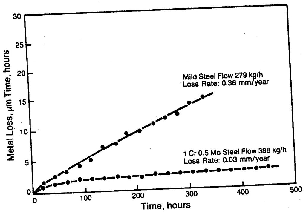
- Use Cr-Mo-Ni combination containing steels which have proven better erosion resistant films
- Alloy cast irons containing nickel and chromium exhibit better performance. Duriron, containing 14.5% silicon, gives excellent performance under severe corrosion conditions.
- Use hard, corrosion-resistant coatings.
5. Case study on erosion corrosion
Case study is partial without images, if you want full case study with images of visual examination, fractography etc., Contact us.
| Case Title | Erosion–corrosion of heat exchanger tubes |
| Part Name | heat exchanger tubes |
| Material | Cu-DHP (CW024A) in soft temper, acc. to EN-12451 |
| Intended Function | coolant circulated and evaporated to cool down industrial water, inlet temperature 16 ˚C, outlet temperature 4 ˚C, rated flow 58.7 m3/h and maximum flow 70.5 m3/h. |
| Service Environment | the R407C coolant tube side, industrial water of pH 6.7 shell side |
| Background History | Before 5 years of operation, number of leaking tubes reached 9 of 118 tubes and the heat exchanger was shut down. |
| Visual Examination of Failure | Figure 8 General view of tube array of the damaged heat exchanger. Some tubes were removed to localise leakages. Visual examination revealed that nature of damage of all the leaking tubes was similar. The tube wall got performed by pits developing from the outside tube surface that contacted with the circulating water. Shape of the pinholes was irregular, of groove or gully nature (Fig. 9a and b) or rounded (Fig. 9c and d). Inside surface of the pits was clean, strongly smoothed, with no corrosion products. This lead to the hypothesis that perforation of the tubes was caused by erosion–corrosion. Apart from the pits, the tube surface was covered by a protecting layer of dark-bronze copper oxide Cu2O. Figure 9 Exemplary pits on outside tube surface: pits with tube wall perforation (a), (b), and pits without tube wall perforation (c), (d). Figure 10 Details of the pit shown in Fig. 9a, longitudinal section A–A. Arrows indicate places with residual corrosion products. |
| Analysis with Mechanism | chemical analysis, fractography, metallographic studies using light and scanning electron microscopes Chemical Analysis: Chemical composition determined by emission spectroscopy with spark excitation was (wt%): Cu 99.97 (as remainder), Ag 0.001, P 0.024, Fe < 0.001, Ni < 0.001, Pb < 0.001, Sb < 0.001, Zn 0.001, Bi < 0.0005, As < 0.001, and S 0.001. Fractography: Figure 11 Location of corrosion products subject to EDX analysis: shallow repassivated pits (a), pit filled with corrosion products and deposits from water (b), and deep pit with corrosion products left in the undercut niche (c). Places subject to microanalysis are marked by arrows and numbers. SEM examination of longitudinal tube sections revealed that the oxide layer covering the internal tube surface was strictly bonded with the substrate, creating sometimes shallow pits filled with corrosion products, see Fig. 6a and b. These products, as well as the substances resembling corrosion products found in the bottoms of the pits shown in Fig. 10 and magnified in Fig. 11c, were subject to local EDX analysis. In the energy spectrum obtained from the corrosion products directly adjacent to the tube surface (see Fig. 11a), reflexes were found from copper, chlorine and oxygen. This means that a copper chloride layer was created under the copper dioxide layer. the granular copper oxide layer on the top of the pits is loosely bonded with the substrate, which means that the repassivated pits became potential places of erosion–corrosion initiation. |
| Conclusion | The copper tubes of the heat exchanger were damaged by erosion–corrosion induced by two factors: disturbed (with turbulences) flow of water containing suspended solid particles and chemical composition of water de-stabilising the protective cuprous oxide layer. Because of high chloride ions concentration in water, shallow, repassivated pits were created on the tube surface covered by a layer of crystalline cuprous oxide, weakly bonded with the substrate. This layer was locally damaged by impingement attack of turbulent water stream containing solid particles. In the so damaged places, flow-enhanced dissolution of underlying copper happened. accompanied by erosion of soft copper, lead to perforation of the tube walls. |
| Recommen -dations | 1. Reduce water velocity in the exchanger, especially after overhaul shut-downs and use proper water filters to minimize content of suspended solid particles. 2. Replace the exchanger tubes made of copper in soft temper by the tubes of aluminium brass or copper–nickel that are less susceptible to impingement attack and pitting, as well as to erosion. |
References
- NPTEL Course by Prof. V. S. Raja, “Aqueous Corrosion and Its Control-lecture-26,27”, IIT Bombay.
- Philip A. Schweitzer, “Corrosion Engineering handbook” CRC Press, 2007
- “Uhlig’s Corrosion Handbook”, Third Edition, 2011 John Wiley & Sons, Inc.
- Batchelor, Chandrasekaran, Margam (2011). “Materials degradation and its control by surface engineering”. 3rd ed., London, Imperial College Press.
- Dr. Derek H. Lister, “Corrosion for Engineers’’, CANDU
- B. Kuz´nicka, “Erosion–corrosion of heat exchanger tubes”, Engineering Failure Analysis, Elsevier 2009