
Friction Stir Welding
According to AWS, “Friction stir welding (FSW) is a ‘solid state forge welding process’, is a type of friction welding which makes a weld joint between two workpieces by the heating and plastic material displacement caused by a rapidly rotating tool that traverses the weld joint”.
In Friction stir welding, no filler wire is used and inert shielding gases are also not required except reactive exotic materials which oxidize quickly in environment i.e. Titanium alloys and some steels.
Heating is caused by both frictional rubbing between the tool and workpiece and by visco-plastic dissipation of the deforming material at high strain rates.
Main fundamental difference between FSW and FW is as below…
| Friction stir welding | Friction welding |
| – The relative motion is between the workpieces and a rotating tool. – Workpieces can be plates, sheets, etc. with butt, lap, t-joint configuration | – The relative motion is between the workpieces that are held in compression. – Generally, there are bar type of workpieces with circular geometry. |
Process of friction stir welding
Friction stir welding uses a non-consumable, rotating tool for local heating of workpiece. The tool rotates and hot-works the material around the weld interface to make a continuous solid-state weld. The tool has the shape of a rod with a concave area (the shoulder) with a pin (or probe) that is coaxial with the axis of rotation.
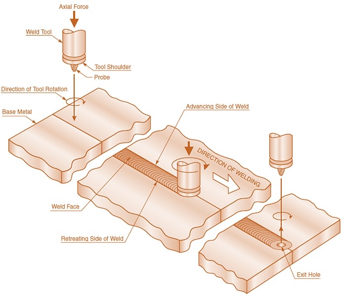
The workpiece is rigidly fastened and are held by a backing plate or anvil, that bears the load from the tool and provides constrain to deforming material at the backside of the joint.
the pin is slightly smaller than the thickness of joint to stop contact with the backing plate and to provide complete joint penetration without defects.
In simple linear butt weld, the workpieces are held on the backing plate with the edges in contact. Then process starts, the rotating friction stir tool is plunged into the weld joint until the shoulder of the tool makes contact with the top surfaces of the plate. The heated material is becomes soft and plastically flows due to frictional rubbing and visco-plastic dissipation. The movement of the tool promotes displacement of the softened material to produce the weld. The hot-worked metal is swept around the tool to produce recoalescence behind the tool.
The tool shoulder provides constraint against the escape of hotworked material, while applying a forging force to the top surface of the weld.
Equipment used in Friction Stir Welding
The equipment used in friction stir welding includes….
- Welding machine with control system,
- Friction stir welding tool,
- Welding fixtures to hold components of the weldment in the correct orientation for proper fitup during welding.
1. Friction Stir Welding Machine
Friction stir welding machine are supported by C-frames, gantries, or vertical structures. They have X, Y, and Z axis with a single-spindle motor. The friction stir welding tool may be tilted with either a manual or powered axis. More complex machines allow for gimballing and tilting of the spindle by the additional axes. which provide ease of welding corner joints and out-of-plane joints.
The motion of each axis is powered by electric motors and gearboxes to provide desired torque, also some machines have hydraulic drives. Friction stir welding machines must have positioning accuracy while welding which is achieved by compensating for deflection with internal deflection control just like feedback systems in CNC machines. Feedback system measures force, speed, position and tries to compensate for any deviations.
Friction stir welding equipment have cooling of the backing plate and tool which can be used to protect the spindle bearings from heat, keep process heat from significantly changing important dimensions of the FSW tool.
Friction stir welding machines are controlled with software based on machine tool controlsMany machines also come with CNC system. Which also have seam-tracking, or vision systems to define or control a weld path.
2. Tool
It is the most important component. Tools are made from wear-resistant materials with good static and dynamic properties at welding temperature. The strength and wear resistance of the tool must be higher than base metal used in the workpiece. i.e., to weld aluminum alloys tool made of tool steel such as H13 is used.
The three types of tools in friction stir welding are…
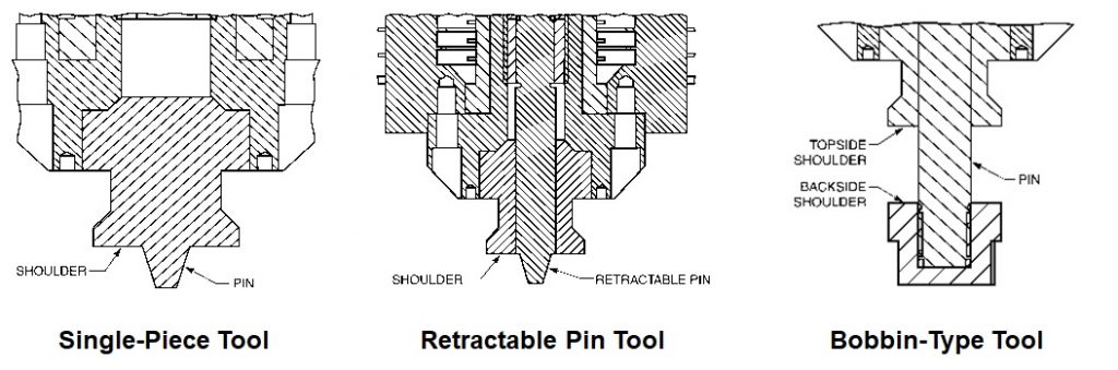
- Single-piece tool: A single-piece tool is a monolithic design consisting of a pin and a shoulder
- Two-piece retractable-pin tool: It provides independent motion of the pin and shoulder in the Z direction. It allows the pin to retract at the end of the weld, and eliminates the keyhole from the plate. It enables the pin to be positioned relative to a backing plate to make sure full penetration, and the shoulder can be operated in load control to ensure proper process hydrostatic pressure, all relatively independent of workpiece thickness.
- Bobbin tool: It has a top shoulder and a backside shoulder. This tool allows for faster welding speeds and eliminates the need for a backing plate. Bobbin tooling eliminates the possibility of a root discontinuity from incomplete penetration by the pin, but bobbin tools are limited in thickness capability because of bending stresses in the pin.

Tool shoulders normally have either a cupped design or a scrolled design. The cupped tool design normally is used with a one-degree to three-degree tilt angle (pushing angle), while the scrolled designs normally are employed at zero tilt. With the tilted arrangement, the rear edge of the tool provides increased compressive pressure to add in recoalescence of the material. The function of the scroll is to force the material in the stir zone to flow inward toward the pin in order to provide the compressive force.
3. Welding Fixtures
Fixturing for friction stir welding is most critical part of the process. The workpieces must be clamped to a rigid backing plate (anvil) and protected to resist the perpendicular and side forces that develop during welding. These forces tend to lift and push the workpieces apart. Fixtures are designed to restrain the workpieces and keep them from moving.
Variables / Welding Parameters of friction stir welding
Friction stir welding has following variables: tool position, spindle rpm, travel speed, and tilt angle of the tool. Other variables are joint design, surface preparation, type of the materials to be joined.
1. Tool Position
It is the position of the tool (Z-axis position). The thickness of the workpiece to be welded decide the type and level of adjustments to be made to the parameters and to the tool design. The tool must be in the correct location to ensure sufficient contact with the top surfaces of the workpieces.
- If the tool is positioned insufficiently deep, shoulder pressure permits loss of constraint, which promotes improper recoalescence of the hot-worked metal under the tool which leads to formation of a running pore on the top side of the weld.
- If the tool is positioned too deeply, the weld area may be thinner than the base metal, the tip of the pin may drag on the backing plate and also overheating the hot worked material in the stir zone.
2. Spindle RPM, Travel Speed
The spindle rpm and travel speed typically decrease with increase in base metal thickness and strength. i.e., high strength Al-alloys require lower spindle rpm and travel speeds.
3. Tilt Angle
The tool angle normally is set either to zero (perpendicular to the weld path) or at a slight pushing angle (1° to 3°). This tilt promotes recoalescence of the material in the stir zone at the rear of the tool.
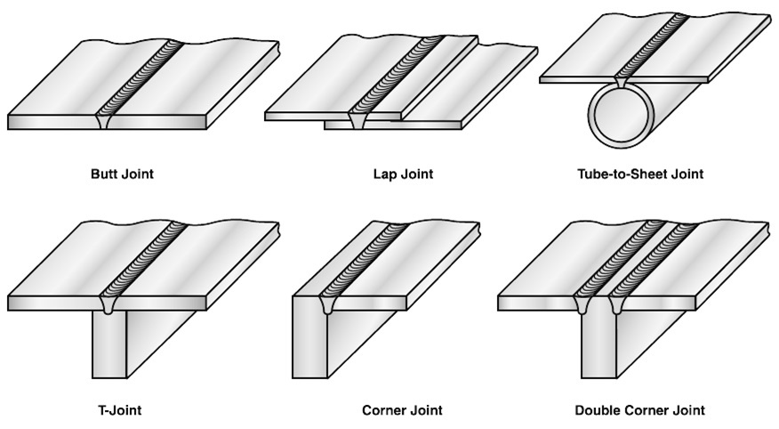
4. Joint Design
Friction stir welding can be used on a range of basic joint designs, as shown in Figure. In any joint design, fixturing must be designed to react to the forces from the FSW tool.
5. Joint Preparation
Friction stir welding generally requires very little to no joint preparation prior to welding. This requirement varies, however, depending on the base metal and the mechanical requirements of the joint. Cleaning the joint area by wiping usually is sufficient.
Advantages of friction stir welding
- Friction stir welding normally is done in a single pass with full penetration and with little or no joint preparation.
- Depending on the workpiece material and thickness, minimal distortion occurs during welding, if proper clamping is used.
- The welds have as-welded mechanical properties superior to fusion welds properties.
- friction stir welding can be done at relatively high processing speeds (except materials with high flow stress at hot-working temperatures, such as steel and titanium alloys). Higher travel speeds can be achieved with friction stir welding than those attained with arc welding, but FSW travel speeds still lack behind laser beam welding.
- Friction stir welding is a machine-tool process so repeatable welds in production applications is possible with little operator input.
- Like all other solid state processes, there are no fumes or spatter, no solidification-related discontinuities, such as cracks and porosity. Also, the process is environmentally clean.
Disadvantages / Limitations of friction stir welding
- The joint is not self-supporting and must be properly restrained.
- If the workpiece is designed in a manner that requires support of the joint, tooling costs might be significant.
Applications of friction stir welding
Friction stir welding is used for variety of metals and alloys, including alloys of aluminum (Al), titanium (Ti), copper (Cu), magnesium (Mg), steel, stainless steel, and nickel (Ni). A number of joint configurations can be used, including butt, lap, corner, and T-joints.
Although higher thicknesses have been welded, still mostly FSW is used to weld Aluminium alloys sheet metals of up to 5-12mm thicknesses.
Aerospace applications, like construction of the main fuel tank of the space shuttles, the booster core tanks of rockets, floor decking for the cargo aircraft, and fuselage and wing sections of Business Class jet.
Marine and rail transportation applications include the welding of fast-ferry decking and sections of subway and rail cars.
Automotive applications of friction stir welding include suspension components and auto body weldments because it does not react adversely to the coating used for this type of assembly.